Mark Zhang

Engineering Documentation

Card Holder

October 5th, Thursday, 2023

This week, I further delved into the Fusion360 and learned the basics of lasercutting with Prof. Ian and Prof. Rogers.

Interactive index

Fusion360 Box Cover & Features Lasercutting Preparation LightBurn Settings Laser Cutting Running First Cut Second cut Troubleshooting & reflection

Fusion360 Box

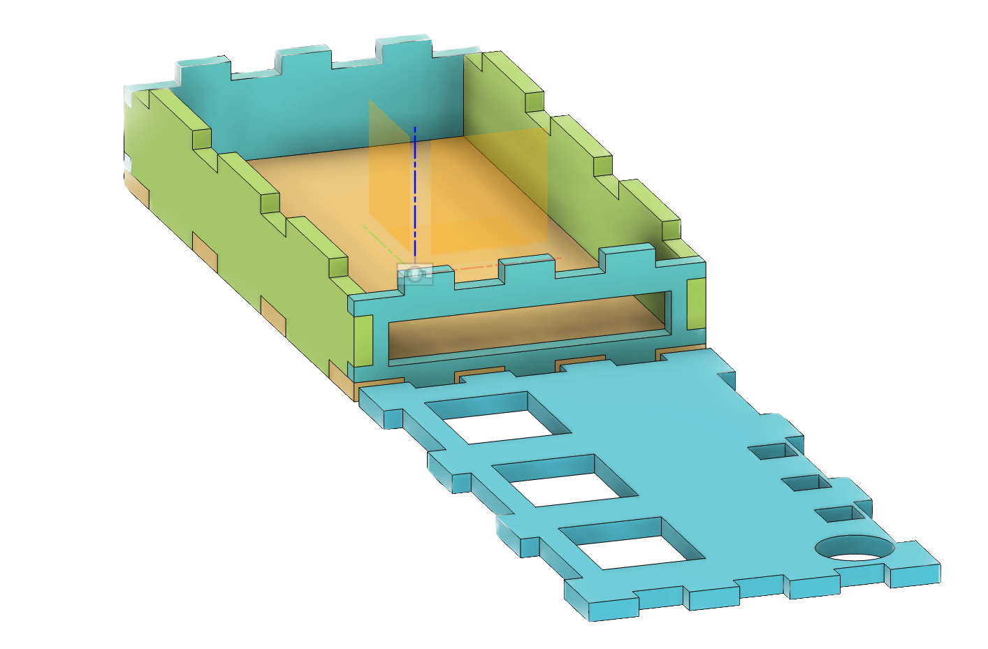
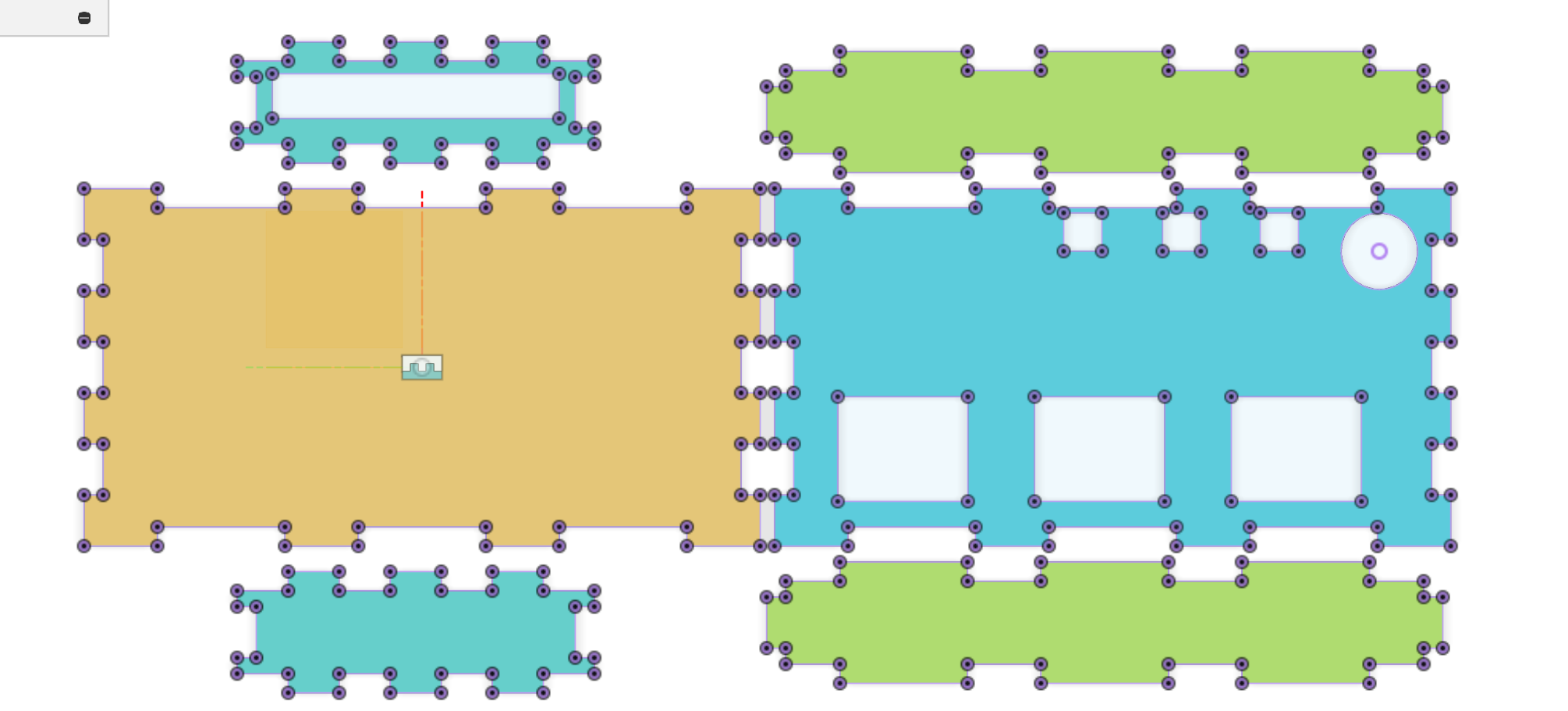
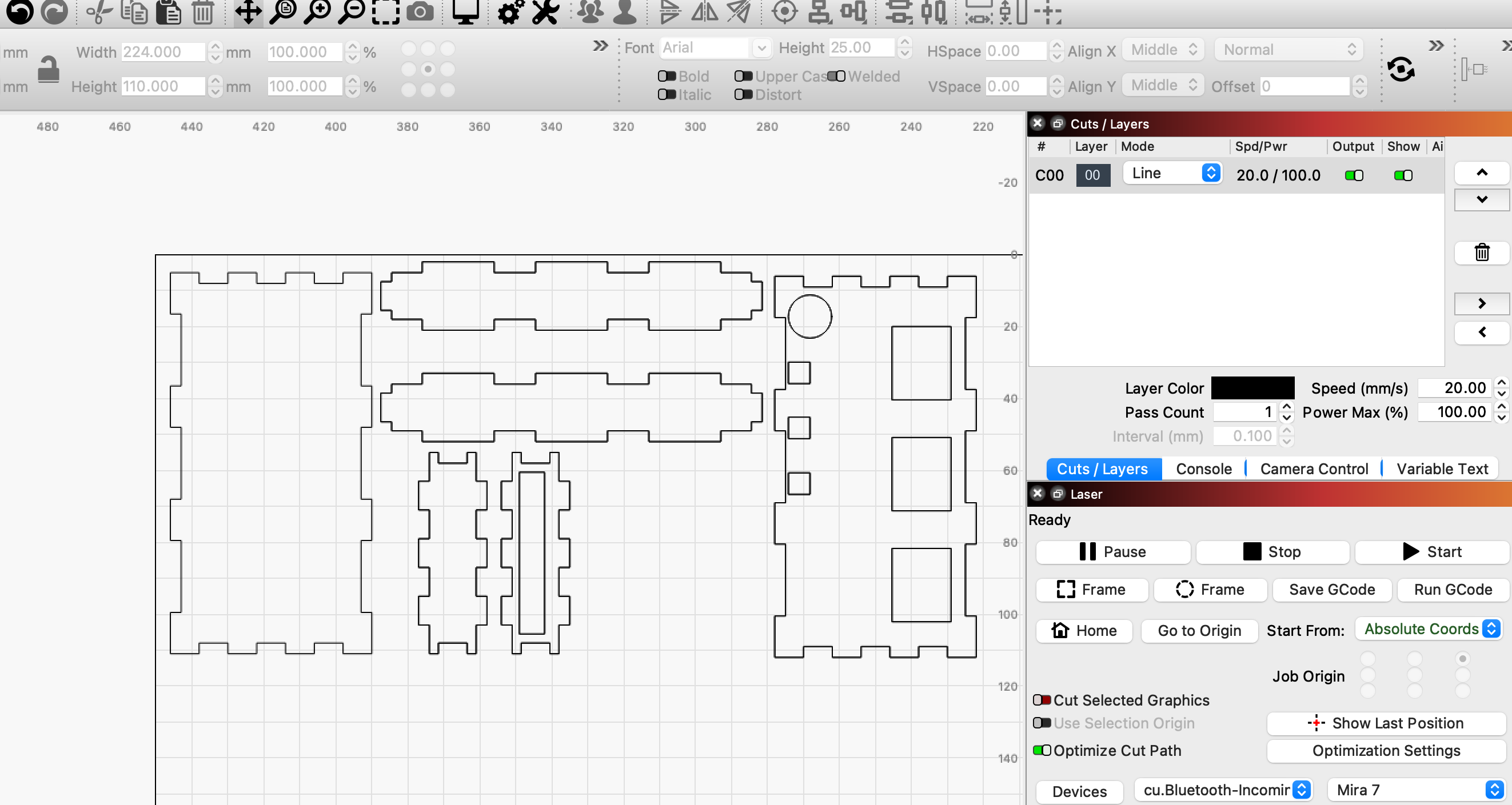
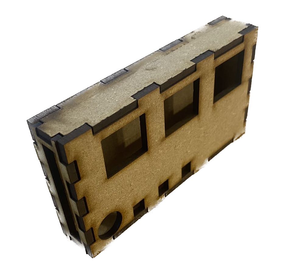
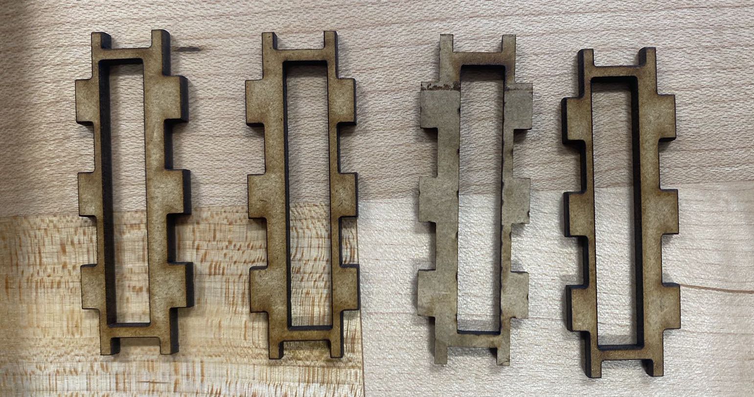
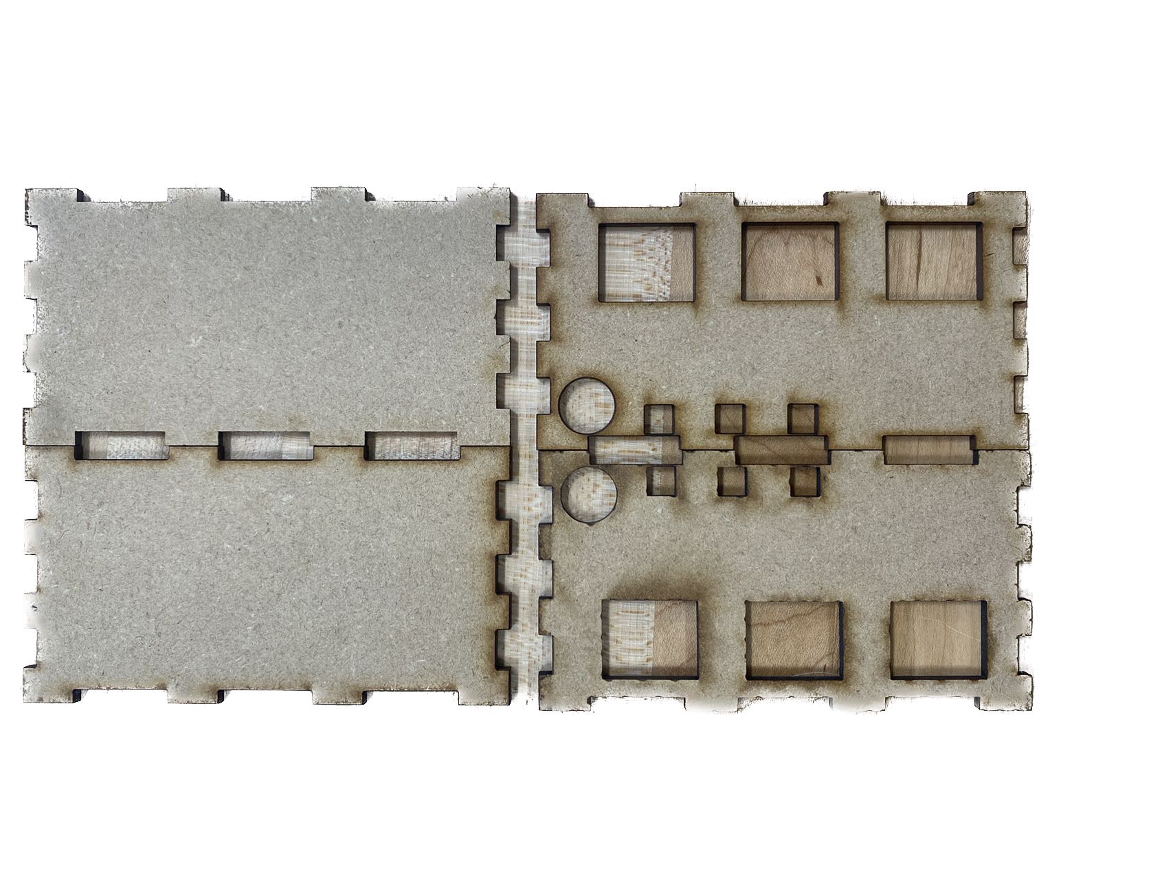
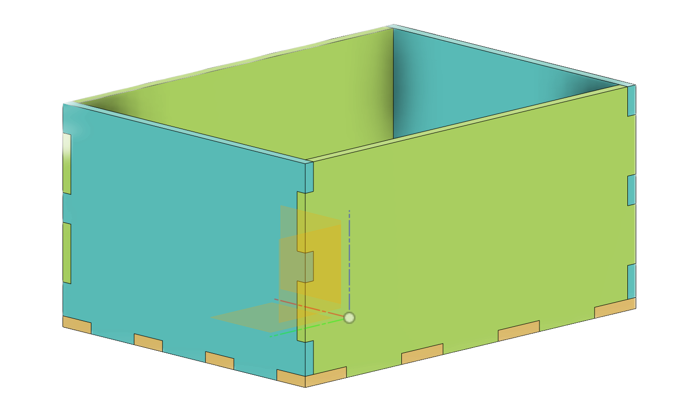
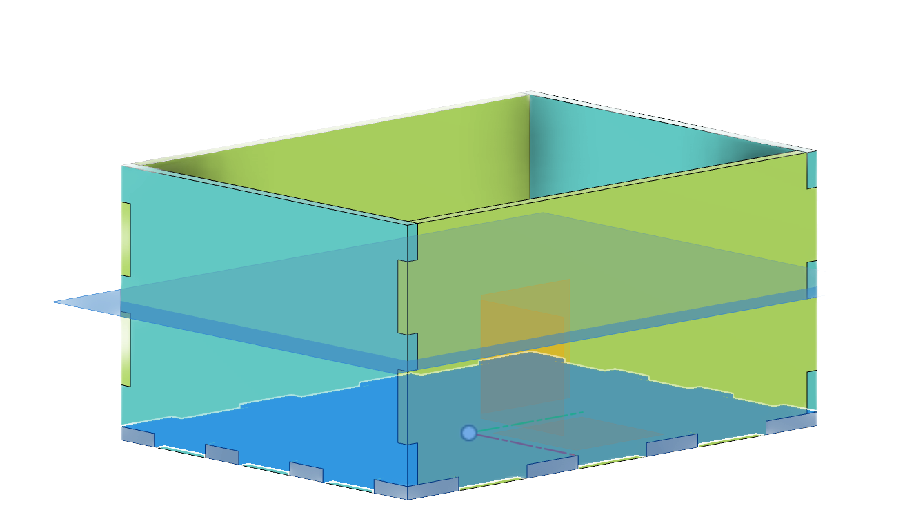
I initially designed a CAD box in Fusion 360 with five facets, an open top, and then added a cover on top. The joints between each pair of sides are finger joints, which are suitable for Lightburn laser cutting. During the design process, I became familiar with several powerful tools in Fusion 360. I defined the width, length, and height as variable parameters, which I then implemented in the sketches. Consequently, once I have the necessary measurements, I can easily update the parameters to fit the circuit board. Another valuable tool is the mirror tool. With its assistance, I only needed to sketch one side for both facets in opposite directions. One important thing to mention is that when I wanted to mirror the bottom for the top cover, I needed to create a construction plane which hovers at the middle of the box first. This is because, unlike the sides, which can use the xz plane and yz plane of the origin as their mirrors, there's no good reference for the bottom-top pair since the origin is on the same level as the bottom. If a mirror image is created around the origin's xy plane, it would be the bottom itself.

Cover & Features

I borrowed the cover design from my project 3. One little challenge is to have the cover fitting into the existed sides and their finger joints. Here I had some hands-on practice of the 'Solid-Combine' tool. There are some interesting functions inside the combine tool and if I want to keep the selected bodies as individual components, I should check 'cut' and 'keep tools'. Besides, one problem I encountered was when I tried to extrude (negatively) a hole for battery wire on the left side, the right side copied my operations and also cut an unnecessary hole. This is the sort of issue which you know how it blatantly errored, that is, my right side is the mirror side of my left side, but it takes time to fix it. I eventually figured out: it's because I drew the rectangle for extrusion directly on the left side body, which is mirror reference. I should have created a sketch outside of the body.

Lasercutting Preparation

Laying components flat is a crucial step in preparing for laser cutting because our ultimate goal is to export them as DXF files. During this process, I explored the 'Joint' feature under the 'Assemble' tab. 'Joint' essentially allows you to align a selected component or body with a point or a line. This feature proves powerful when disassembling my box and laying the components flat on the same plane. I had tried several methods to export a Fusion 360 design as a DXF file, but unfortunately, none of them worked out. However, Professor Rogers came up with an elegant solution. What Professor Rogers suggested to me was to create a projected sketch on the face of each component. These vector-based sketches can then be exported as DXF files.

LightBurn Settings

Well, frankly speaking, even though this is my first time using LightBurn, I have to say I hate the fact that LightBurn lacks the functionality of automatically arrange and fit vector shapes into material size. So once you collectively import all your DXF files, you would get a complete mess of overlapped vectors. I did some searching online and people were saying the same that there's no such arrange tool, which is quite disappointing. For this project, I only had 6 DXF files to import. But imagine what if it was a greater project with hundreds of components and I had to manually import them one by one...Bruh. The preset for MDF board, the material I used, was speed 20% amd power 100%. Prof. Ian reminded me some safety precautions; ventilation, alarm, and emergency stop button and guided me through the material optimization. After connecting with our Laser machines Mira 7 and Mira 9, I was good to go.

Laser Cutting Running

Here's how the laser works

First Cut

My first attempt is not perfect. The finger joints are too loose to hold each other stably. The tolerance in my CAD model is inadequate because each joint is created solely by the complementary cut of the others. However, I should have considered that the cutting process would involve a loss of material, resulting in joints smaller than expected. I measured the gap between the concave joint and the bulge joint to be approximately 0.4 millimeters. Other than that, the major dimensions fit the circuit board.

Second cut

Based on the gap, I extruded 0.2 millimeters on each side of the concave joint to compensate for the material loss during cutting. The second cut turned out to be a bit tight, and I accidentally broke the top bridging on the left side. However, it's not a significant issue. Recognizing that this side is particularly vulnerable, I created four additional substitutes. In the end, the overall quality of the second cut is great, with the joints tightly fitting together.

Troubleshooting & reflection

I've encountered relatively little issues in this project compared to the previous clock project. It's most likely because i alrady have the best-fit measurements for the cover so i don't have to experience the annoying iteration, although most of the time iteration is the most important step for engineering a product of good quality. Besides, I feel Laser cutting can achieve high precision and fine details, making it ideal for intricate vector-based designs. I'm glad that now I'm more proficient with Fusion360. The project and inspect tools are really useful for separating components, preparing for the lasercutting.

Copyright © Mark Zhang 2023